
Hydraulic systems in heavy equipment are designed utilizing certain principles for performing work using multiple components. For instance, motors activate pumps; the pumps pressurize hydraulic fluid that passes through tubes to actuators. As an example, the actuators in an excavator move the arm or bucket. The fluid passes through filters, is recycled through the system, and circulates back to the pump.
Hydraulic systems are very sophisticated and utilize a variety of individual components, such as:

· Counterbalance valves
· Hoses
· Pumps
· Filters
· Hydraulic Cylinders
· Tubes
· High Pressure Seals
· Fittings
· Valves
· Check Valves
The materials used to manufacture hydraulic system components must be exceptionally tough and durable to withstand extreme conditions. These materials include:
· Carbon Steel
· Synthetic and Rubber Hose Material
· Stainless Steel
· Woven Wire
Some systems may include titanium components, which is typically used in extreme high-pressure systems and may operate up to 50,000 PSI or more.
Safe operation of a hydraulic system starts with the initial design. Maintenance in the field can only be done effectively if the system is properly designed in the first place. We change the oil in our cars for clean lubrication of the engine. Imagine if the engine’s

design restricted flow of oil to the pistons, it wouldn’t
take long for your engine to seize up. To correct the problem, it would take more than performing typical maintenance, you would be facing an entire rebuild of the engine.
When designing hydraulic systems to ensure safe operation, safe maintenance, minimize unscheduled maintenance and reduce downtime, there are many important considerations to follow. Design engineers should be trained and educated to follow safe and efficient system design. However, it is important for maintenance engineers to also have knowledge of what goes into it.
Selecting the correct inside diameter of fluid piping, such as steel tubing, steel pipes and hydraulic hoses
Piping should be sized to avoid drops in pressure. Unstable flow causes unnecessary friction between the walls of the piping and the fluid, ultimately creating lost energy in the system which will raise the temperature of the fluid. This is due to excessive fluid velocity which causes turbulence and unplanned pressure drops. By maintaining a practical fluid velocity, pump inlet conditions will be controlled which will reduce the potential of excessive heat.
Recommendations for maximum fluid line velocities are:
- 2 to 4 feet per second for inlet or suction lines
- 10 to 15 feet per second for return lines
- 15 to 20 feet per second for pressure lines operation from 500 to 2,000 PSI
- 25 feet per second for pressures of 3,000 PSI
The following formulas should be used to ensure conductors are properly sized:
V=0.3208 *Q/A
V = velocity in feet per second
Q = Flow rate in gallons per minute
A = Area of the conductor (piping) in square inches
To find the area of the piping use:
A=0.7854*D2 (D being inside diameter in inches)
To verify if the correct size of the pressure line convert the formula as follows:
D=√{(0.4085*Q)/V} (for example a 10 gallon per minute system that has a maximum velocity of 20 feet per second the inside diameter of the tubing should be 0.452 inches or a 1⁄2-inch diameter pipe)
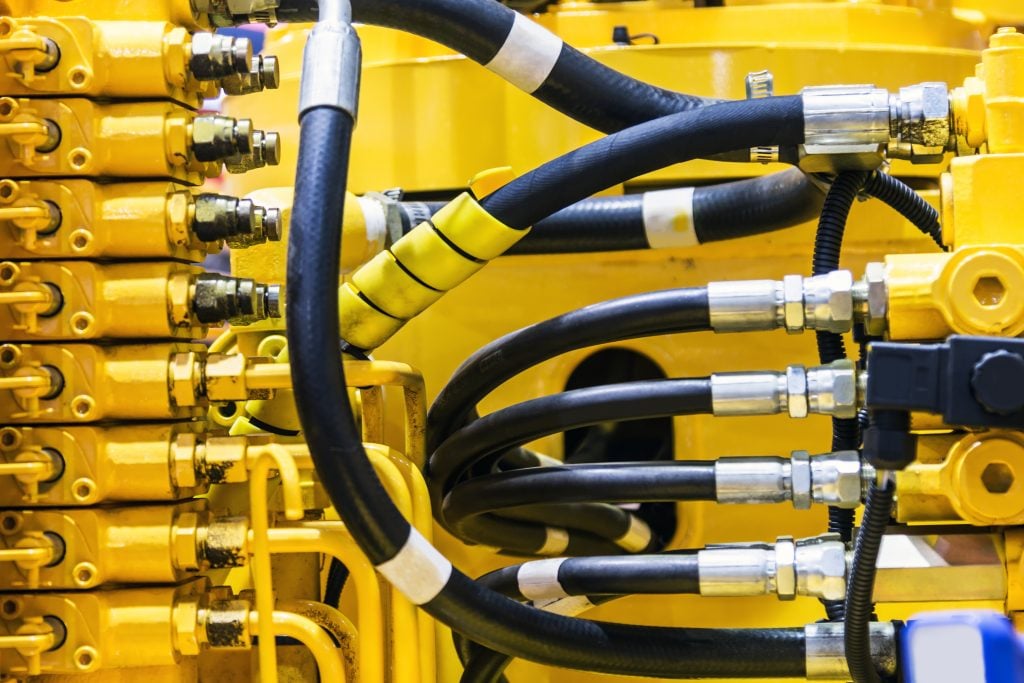
The purpose of hydraulic hoses is to allow for movement of components on heavy equipment and industrial power units. Hoses are used where rigid lines will crack or break under these conditions. They are found on a pump’s suction lines, discharge and case drain. You can use the hose’s layline as a visual index when routing and tightening the assembly to ensure the hose is not twisted or kinked. Use the layline to determine the right hose, its required size and ensure it is plumbed correctly. Hydraulic hoses should be visually marked in accordance with SAE J517. Though all piping on new equipment, including hoses, is unlikely to be shipped with any deformity, it’s important to give a visual inspection prior to putting into service. Even a 7 degree twist can cause up to 90 percent loss of the hoses’ service life.
Selection of Fittings and Connectors
The proper selection of connectors or fittings is imperative and must be leak-free. Hydraulic systems commonly incorporate one or all of three styles of fittings:
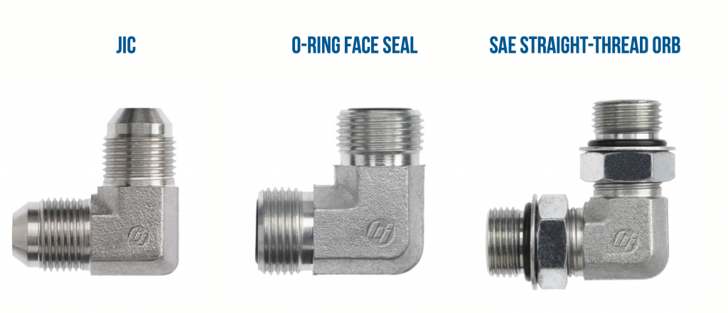
Fittings seal the hydraulic fluid within the system with either all-metal fittings that have metal- to-metal connections, or O-ring fittings which contain the pressurized fluid with compressed elastomeric seals. In both cases it is imperative that the fittings be tightened to system specifications to form a high-pressure seal. Over tightening will cause cracks, leaks or even a rupture which can lead to a dangerous system failure.
Designing Hydraulic Fittings and Flanges into a System
Along with hose, tube and pipe conductors every hydraulic system incorporates a series of fittings, and often flanges, to connect the conductors to actuators, pumps, valves and other components. Because of the need for system maintenance, removable fittings are required, except for certain specialized systems.
Pipe Fittings
All-metal pipe fittings have threads which have a high likelihood of leaking because they are often over-tightened, which distorts the thread and/or causes cracks that allow for leak paths. In addition, metal pipe threads will often loosen when exposed to wide fluctuations in temperature or even small amounts of vibration. In fact, most design engineers consider metal-to-metal connections to be obsolete for use in hydraulic systems.
JIC Flare-Type Fittings
JIC fittings are the type most often used in hydraulic systems. Because the 37° flare fitting’s tapered end seats into the flared end of the tubing it provides a positive seal. JIC fittings are designed for use in systems with operating pressures of up to 3,000 PSI and temperatures from 165° to 400° F, that utilize thin to medium-wall thickness tubing. Thick-wall tubing is not applicable because it is difficult to form the flare. JIC 37° flare fittings have many positive features, such as:
- Saving space because they are more compact than others
- Can be easily adapted to metric
- Are readily available
- Are comparatively economical
Drain Lines, Valves, Filters, Lines and Pumps in a Hydraulic System
Sizing case drain lines. Typically, hydraulic motors and pumps have hoses that run to a case drain in order to drain excess internal oil from the motor. Having a case drain usually requires running motors in series to avoid damage. If the case drain line is undersized on a hydraulic pump (piston) it can cause the pressure in the case to be too high. As the pump’s life depreciates its volumetric efficiency will decrease, which in turn will increase leakage from the case drain line. If there is extreme case pressure it can cause the piston shoe to lift off the swash plate. This will cause damage that will force the pump to stop working. Go by the case drain port size or up-size it. It is important to make sure the case pressure is below the max rating, which if necessary, can be adjusted at the case drain port size, or increase the size of the port. Case pressure can also become too high at:
- The reservoir well above the pump
- The pressurized tank
- A temperature that is too low for the viscosity of the oil being used
- A viscosity that is too low for the operating temperature
Alleviate pump failure by mitigating cavitated or aerated components. If air is allowed to enter the system, the aeration will produce erosive damage when passing through the pump. In addition, cavitation can cause insufficient pump inlet, which can damage the pump. Either of these conditions can be very destructive.
- Aeration is caused by air entering the pump inlet and mixing with the fluid. Low pump pressure at the inlet will cause air bubbles to expand and, as the aerated fluid reaches the pressure side of the pump, the bubbles will disintegrate and implode which causes internal erosion of the system.
- Similar to aeration, extreme vacuum in a component will cause cavitation, which allows vapor bubbles to form in the fluid, ultimately damaging the pump.
Either of these conditions will cause pump noise to go up. If the system is allowed to continue to operate the pump will eventually fail. To safeguard against this problem in the design phase any source of air must be contained and the potential of vacuum at the inlet must be alleviated.
It's important to design for flow amplification when sizing filters, lines and valves
If the proper size of the lines is not selected to handle a higher flow rate, unwanted heat will occur causing damage to motors or other components. When designing a hydraulic system valves must be selected and sized correctly, or flow will be restricted which can cause it to unseat. In addition, the filter must be sized
correctly, or the bypass valve may open causing some of the fluid to be unfiltered or cause a flow surge that could collapse the element.
The control of pressure in a system is paramount in the design. Hydraulic pressure control valves are essential in preventing leaks or bursting of pipes, hoses or tubing. This is largely dependent on the proper selection of pressure control valves, which may include:
· Relief valves
· Counterbalance valves
· Unloading valves
· Sequence valves
· Reducing valves
· Needle valves
Needle valves are common in low-pressure hydraulic systems and are often automated, connected to a hydraulic motor or air actuator that automatically opens and closes the valve. Manual and automated valves of all types provide precise control of the flow rate and are used for regulating the flow of fluid in the system. However, in some cases a needle valve can cause excessive heat to build up and waste energy if not properly designed into a system. For instance, if the system is operating at 10 gallons per minute, pressure will flow to the actuator if the relief valve is set at less than the 3,000 PSI. If the pump is producing 10 gallons per minute and it becomes necessary to slow the cylinder down, the needle valve must be adjusted down to restrict the flow. As the flow to the cylinder is restricted, the relief valve will open allowing the flow to go over it at 3,000 psi wasting energy in the form of heat. At 3,000 PSI, with as little as 2 gallons per minute over the rated flow, it can generate as much as 9,000 BTU. Excessive heat will severely damage hydraulic components and waste energy.
Important Guidelines in the Design of Hydraulic Systems
The design of hydraulic systems for heavy equipment and other machinery must take into account how and where the system is to be used. In accordance with ISO 14121-1, a risk assessment must be conducted to ensure there are not any predictable risks in the design that could carry over into the field. Reasonably foreseeable misuse shall not cause hazards. If any portion of the design is unable to foresee potential risks in the field, then safeguards and warnings must be integrated into the system following safety standards as identified in ISO 12100. As further precaution, ISO 13849-1 is used in the design of control systems.
Some fundamental considerations must be followed when designing hydraulic systems and establishing their specifications
1. Piping and components
- The selection of all system piping, tubing, hoses and components must be specified to make sure they are safe for the intended application and will function in accordance with their rated limits. It is especially important to ensure the reliability of all components so they do not present a hazard if they should happen to fail. For instance, specifying proper fitting torque, hose assembly and flange selection, plus any other component that has the potential of causing physical harm or damage to equipment.
Selecting and installing components must follow the supplier’s instructions. However, in some cases separate testing or prior experience may confirm the suitability of different components, their installation and their application.
For consistency, and to make sure safety is built into every system, its piping, connections and components should conform to International Standards.
2. Potential leakage
- In the event of external or internal hydraulic leakage, measures must be put into
place to minimize and contain it and ensure it does not cause potential hazards.
3. System temperature
- The operating temperatures of the system or

system components must not exceed the limits specified for safe handling or usage. Warnings and other safeguards should be put into place where applicable. This includes designing systems in a manner that ensures people are protected from high surface temperatures by isolating the component, posting warnings or guarding the location in accordance with ISO 13732-1.
4. Maintaining designated system pressure
- The system and its components must be designed and protected from the possibility of the pressure exceeding the designated maximum allowable working pressure. This includes maintaining the rated pressure of parts within the system if there is the possibility that an increase may be hazardous.
If system components, fittings or piping are able to be disconnected or resealed, that can trap fluid which has the possibility of increasing or decreasing pressure due to a change in fluid temperature or load. There must be a method for limiting a potentially hazardous change in pressure by incorporating relief valves, pressure-compensator pump controls or other methods of safely diverting pressure.
It is imperative that all hydraulic systems are designed to restrict potential fluctuations or surges in pressure that may be hazardous to individuals or equipment. This includes excessive pressure that can cause external loads on actuators to exceed specification.
5. Mechanical movements
- Any mechanical movement, including but not limited to the result from acceleration, deceleration and lifting or holding materials, must not incur the consequence of being a hazard to people or property.
6. Managing noise
- In accordance with ISO/TR 11688-1 the design of hydraulic systems should take into account the anticipated noise that will be generated in application and steps taken to minimize noise that could be hazardous, or within reason, cause an unnecessary nuisance to the environment.
7. A hydraulic system's functional and operational requirements
- When designing a hydraulic system, clear operational specifications must be identified for the user, such as:
- Safety, emergency and energy isolation
- Lifting specifications
- Protective coatings
- Types of allowable fluids
- Working ranges of:
- Flowrate
- Pressure
- Temperature
Conclusion
Making the decision to leverage newer and safer technology
Hydraulic technology has advanced incrementally and steadily over the past decades in the three primary areas of the control system: the technology in actuators (output), operator joysticks (input) and sensors (feedback) have become more reliable and

cost effective.
The effects of technological improvements on the human element should not be ignored. Key developments have been most effective when operating equipment with higher ease of use and reduced operator fatigue. In the past it took a highly skilled operator to control the speed of multiple functions. However, the introduction of pressure compensated load-sensing (PCLS) systems allows for greater efficiency and ease of use.
Adopting more sophisticated equipment and the new technology that goes with it is an important business decision. Newer and more advanced equipment must achieve improved productivity and reduced fuel consumption in order to justify the investment. Businesses must make the decision to embrace new technological efficiencies in hydraulics to positively affect their bottom line while making the operator’s job safer and easier.
SOURCES:
Grading & Excavation Contractor
Hydraulics & Pneumatics 1
Hydraulics & Pneumatics 2
Machinery Lubrication
Society of Tribologists and Lubrication Engineers
Swedish Institute of Standards